
 Home
>
products
>
Smart BMS System
>
Home
>
products
>
Smart BMS System
>
|
| Place of Origin | China |
| Brand Name | XUWEN |
| Certification | CE,FCC,RoHS,UN38.3,MSDS |
| Model Number | 20a 30a 40a 50a 10s 36v Smart BMS System |
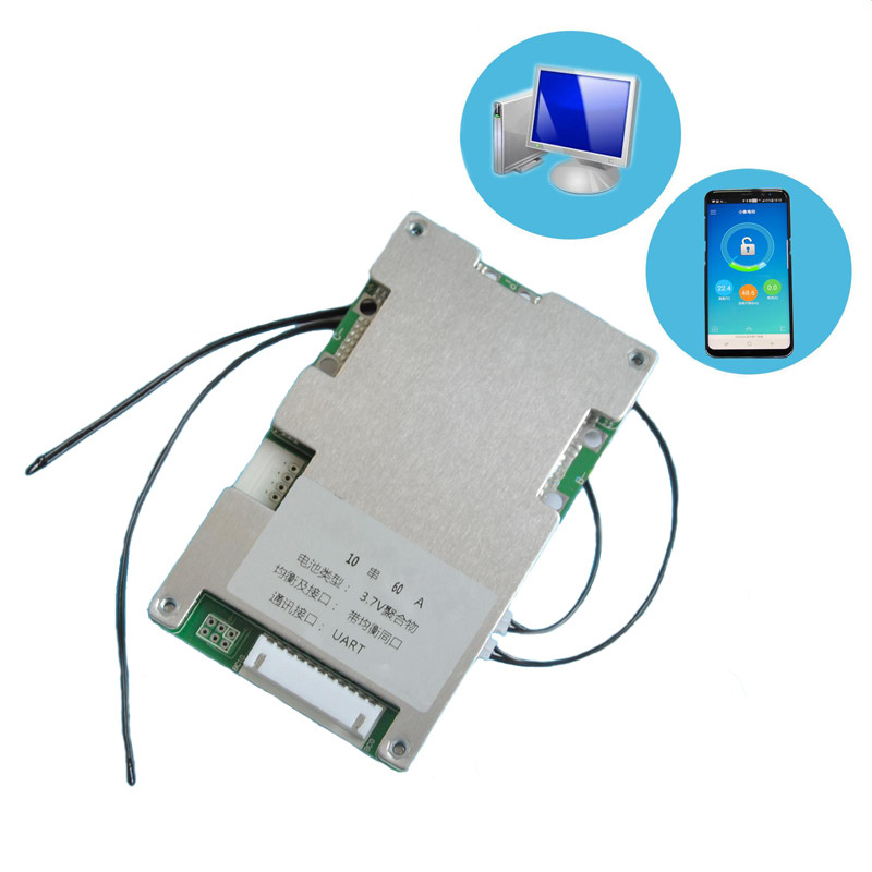
Smart Battery Management System 20a 30a 40a 50a 10s 36v Smart BMS System Pcb Pcm With UART Communication
| Function | Test Project | Test Condition | Specification | Unit | ||
| Min | Middle | Max | ||||
| Over charge protection | Over Charge Protection Voltage | At charge off | 4.22 | 4.25 | 4.28 | V |
| Over Charge Protection Delay Time | / | 500 | 1000 | 1500 | mS | |
| Over Charge Protection Release Voltage | / | 4.1 | 4.15 | 4.2 | V | |
| Balance Function | Start Voltage | / | 3.57 | 3.6 | 3.63 | V |
| Start Voltage difference | / | 30 | mV | |||
| Balance current | / | 50 | 60 | mA | ||
| Charge current | Normal charge current | / | 60 | A | ||
| Over charge current | Over charge current | / | 65 | 70 | 75 | A |
| Over charge current delay time | / | 2 | 5 | 8 | S | |
| Over charge current release | / | 15 | S | |||
| Over temperature protection when charge | High temperature protection | / | 62 | 65 | 68 | ℃ |
| High temperature charge release | / | 52 | 55 | 58 | ℃ | |
| Low temperature charge protection | / | -12 | -10 | -7 | ℃ | |
| Low temperature charge release | / | -3 | 0 | 3 | ℃ | |
| Over discharge protection | Over Disharge Protection Voltage | At discharge off | 2.42 | 2.5 | 2.58 | V |
| Over Discharge Protection Delay Time | / | 500 | 1000 | 1500 | mS | |
| Over Charger Protection Release Voltage | / | 2.7 | 2.8 | 2.9 | V | |
| Discharge current | Max continuous current | / | 60 | A | ||
| Over current Protection | Over Current Protection 1 | / | 65 | 70 | 75 | A |
| Over Current 1 Delay Time | / | 3 | 5 | 7 | S | |
| Over Current Release | Over Current Release Condition | / | 32 | S | ||
| Over current Protection | Over Current Protection 2 | / | 80 | 90 | A | |
| Over Current 2 Delay Time | / | 100 | 320 | 500 | mS | |
| Over Current Release Condition | / | 32 | S | |||
| Short Circuit Protection | Short Circuit Protection | / | 150 | 200 | 250 | A |
| Short Circuit Protection Delay Time | / | 200 | 400 | 800 | uS | |
| Short Circuit Release | / | Cut Off Load Delay Time 32S | ||||
| Over temperature protection when Discharge | High temperature protection | / | 67 | 70 | 73 | ℃ |
| High temperature discharge release | / | 57 | 60 | 63 | ℃ | |
| Low temperature discharge protection | / | -12 | -10 | -7 | ℃ | |
| Low temperature discharge release | / | -3 | 0 | 3 | ℃ | |
| Internal Resistance | Internal resistance of discharge circuit | / | 10 | mR | ||
| Self-power consumption | Normal Mode | with Communication | 20 | mA | ||
| Sleeping Mode | / | 150 | 200 | uA | ||
| Sleeping Delay Time | / | 8 | 10 | S | ||
| Remark: Above data is for sample only. Customer could adjust the Data through connect computer | ||||||
![]()
RFQ
1.What is the common port and separate port? what is the difference?
We take 13S 48V 15A BMS as an example, common port 15A means your charge cathode and discharge cathode are connected in the same point end(our P-), charge cathode and discharge cathode are used in the common connection
port, so the charge current and discharge current are the same 15A. while the separate port is separately connected by charge cathode (C-) and discharge cathode (P-), so the charge current and discharge current are different, discharge current 15A, charge current 8A.
2.What is the balance function?
The working principle and function are as followings, when your one cell voltage is upto alarm voltage(Li-ion upto 4.18V, LifePo4 upto (3.6V), then the cell Balance starts to work, balance resistance starts discharge with 35ma(when balance discharge starts to work, BMS will starts a little heat up, which is the normal reflection), the cell is in both charging and discharging status, and others which are not reached to alarm voltage(Li-ion 4.18V, LifePo4 3.6V)are only in charging status, no discharging, when the fast cell voltage is reached to alarm voltage (Li-ion 4.25V, LifePo4 3.75V) BMS starts off power protection, all the other cells are all in stop of charging, this process will enable your battery charging in balance current, and your battery voltage are in balance status, but when your cell voltage difference are in a big range, then balance can not be functionning well
3.The relationship between Battery capacity and BMS current?
There is no direct relationship between Battery capacity and BMS current, big capacity doesn`t mean a big battery, but rely on continue current, that is to say if your engine is powerful, your should choose high current of BMS, it is not relied on battery capacity.
4. What type of charger should I choose?
Lithium battery must choose specific charger, do not use Charger for Leadacid battery, for leadacid charger may have MOS with high pressure breakdown protection, which will not protect of BMS over charge. Life Po4 battery charger voltage=battery string No.X3.6V, while Li-ion battery charger voltage=Battery string No.X4.2V.
5. What current BMS should I choose ?
Take 10S 36V as an example: what current BMS you choose is relied on your E-bicycle Motor power and current limitation of controller. eg., choose 15A for below 350W, 20A for below 500W, 30A for below 800W, 60A for Below 1000W, higher than 1200W are contact with our service specialist for suggestions, one inall, continue current shall be higher than current limitation in Controller.
6. Whether my BMS damaged?
if you want to judge if the BMS is damaged, please take the folowing steps, to test if each cell voltage is the same with
voltmeter? if the cell voltage difference is over 1.0V, the fault is displayed that it cannot run far, no power supply at the
start range, short charge time, all these issues are almost caused by battery cells, if BMS damaged is displyed as no charge, no discharge, no discharge while the battery has voltage.
Contact Us at Any Time

